Tutorial
The IPM repo features multiple components. The main ones are:
The IPM Library, which is a vectorized implementation of the IPM projection. It exposes a Python API, that can be used directly.
The IPM Service, which wraps the IPM library in a ROS 2 service. It can be used to perform language-agnostic IPM projections using normal ROS interfacing.
The IPM Image Node, which can be used to directly project images (e.g. from a camera) or masks onto a given plane. It essentially listens to an image topic, related camera info, and TF to publish a point cloud containing the projected pixels.
IPM Image Node
The IPM image node is a ROS 2 node that can be used to directly project images (e.g. from a camera) or masks onto a given plane. It is the most user friendly way to use the IPM projection and is the recommended way to use the IPM projection in many cases.
The IPM Library and the IPM Service are more flexible and can be used to project points in a more general way. They are e.g. used for the Soccer IPM node, which projects soccer_vision_2d_msgs from the soccer_interfaces package onto the ground plane.
In this tutorial, we will use the IPM image node to project a full image onto the ground plane. To do this in a more or less realistic way, we will use the turtlebot3 simulation in Gazebo. It will be assumed that you have a working ROS 2 installation and performed the steps in Installation. Also don’t forget to source your ROS 2 installation as well as the IPM workspace.
First of all, we need to install the turtlebot3-gazebo ROS 2 package.
sudo apt install ros-$ROS_DISTRO-turtlebot3-gazebo
In addition to that we need to clone the turtlebot3 ROS 2 packages from GitHub into our colcon workspace source directory (e.g. ~/colcon_ws/src).
git clone git@github.com:ROBOTIS-GIT/turtlebot3.git
Now we can build our workspace using the following command:
colcon build
After that, we need to source our workspace so we know about the new packages.
source install/setup.bash
Then we can launch the simulation using the following command:
TURTLEBOT3_MODEL=waffle_pi ros2 launch turtlebot3_gazebo turtlebot3_world.launch.py
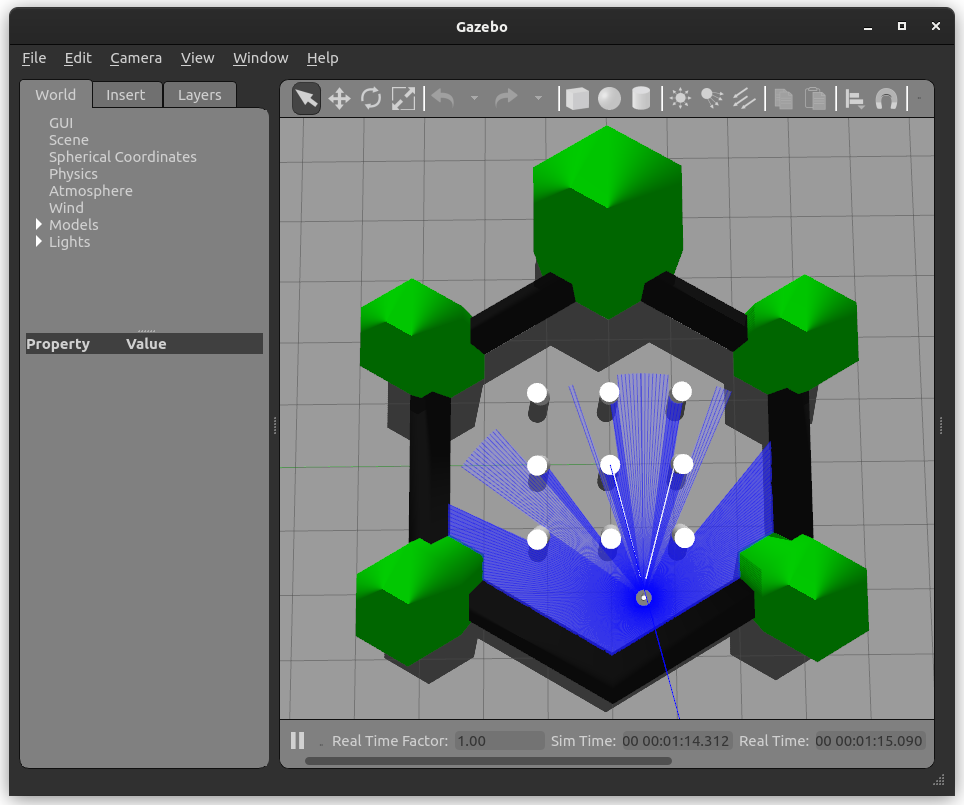
You should see the following view in Gazebo:
Now we can launch the IPM image node using the following command. Note that we are remapping topics to be compliant with the turtlebot3 simulation topic names. We also set two parameters to define the output frame and the type of the input image. The projection of full RGB images is not very common except for visualization purposes, but it is a good way to test the IPM image node. Normally one would e.g. project only the non-zero points of a mask segmenting e.g. road markings onto the ground. This can be done by setting the type parameter to mask. To increase performance, one can also set the scale parameter to a value smaller than 1. This results in fewer points being projected and thus less computation time.
ros2 run ipm_image_node ipm --ros-args \
    -r camera_info:=/camera/camera_info \
    -r input:=/camera/image_raw \
    -p type:=rgb_image \
    -p output_frame:=odom
You can add the following XML to a launch file to launch the IPM image node.
<launch>
    <node pkg="ipm_image_node" type="ipm" name="ipm_image_node" output="screen">
        <remap from="camera_info" to="/camera/camera_info"/>
        <remap from="input" to="/camera/image_raw"/>
        <param name="type" value="rgb_image"/>
        <param name="output_frame" value="odom"/>
    </node>
</launch>
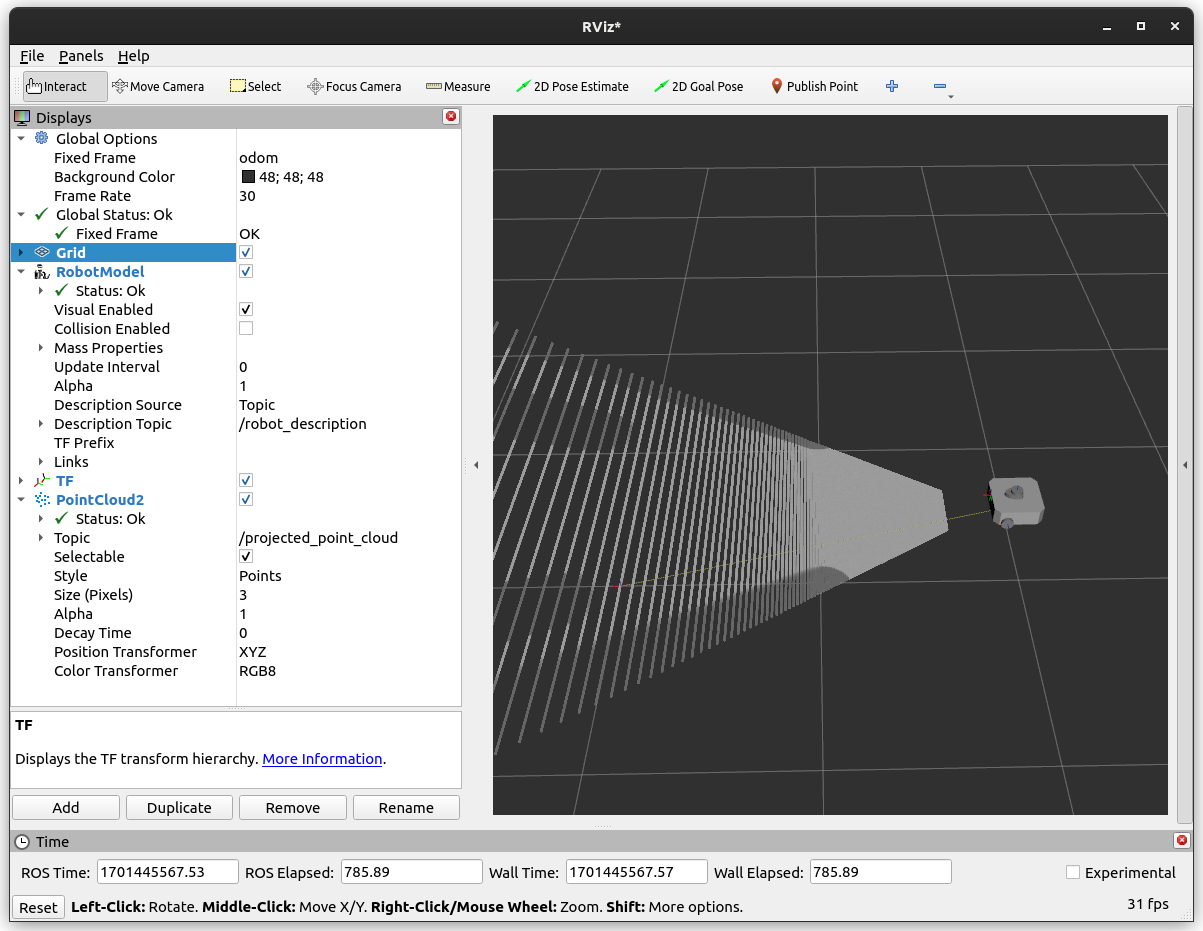
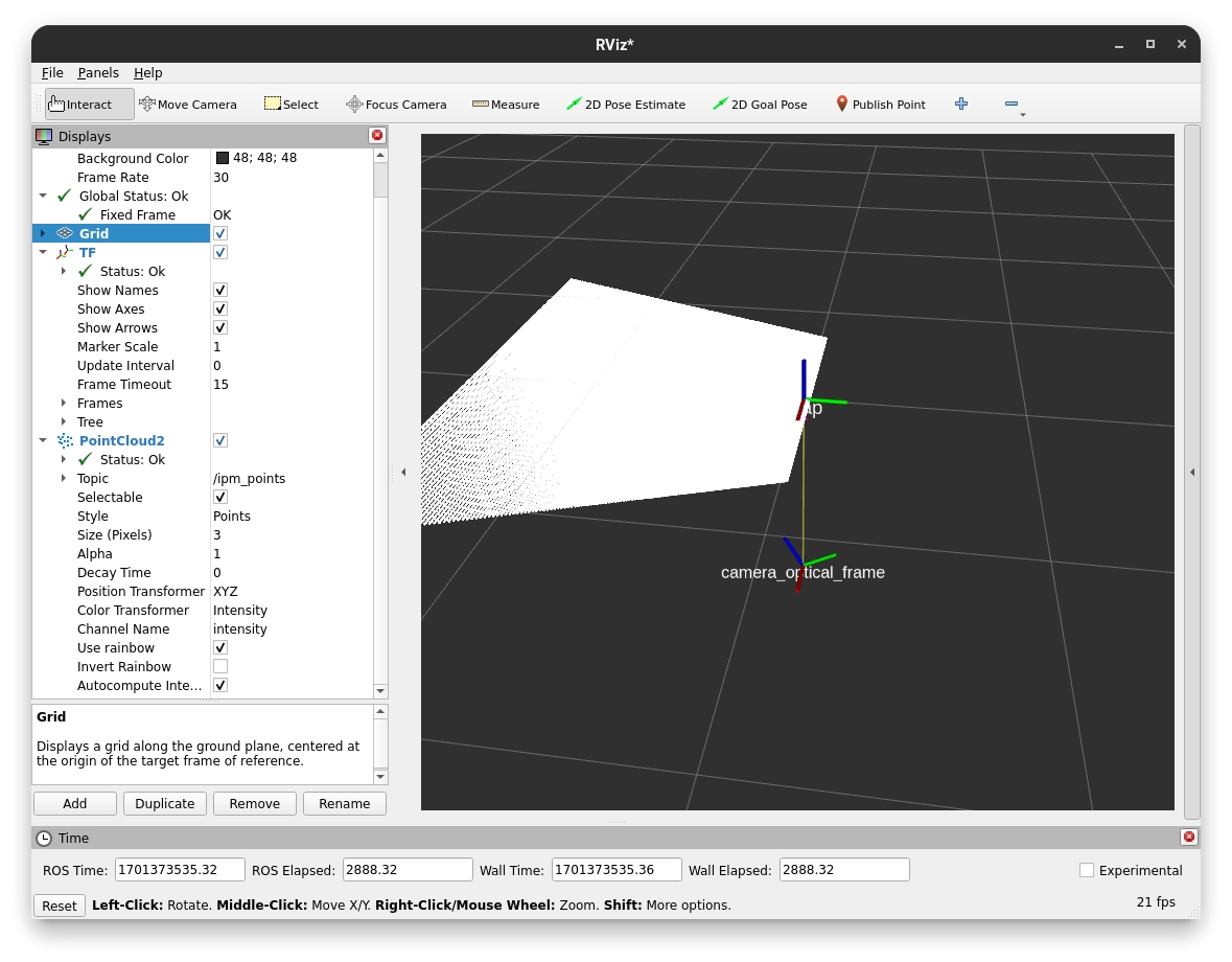
Now we can open RViz2 and add the point cloud display to visualize the result on topic /projected_point_cloud. For better visibility, you can set the style to Points. You also want to set the Fixed Frame to odom to see the result in the correct frame. Adding the robot model as well as the TF display can also be helpful to see the spatial relationship between the robot and the projection plane.
You should see the following view in RViz:
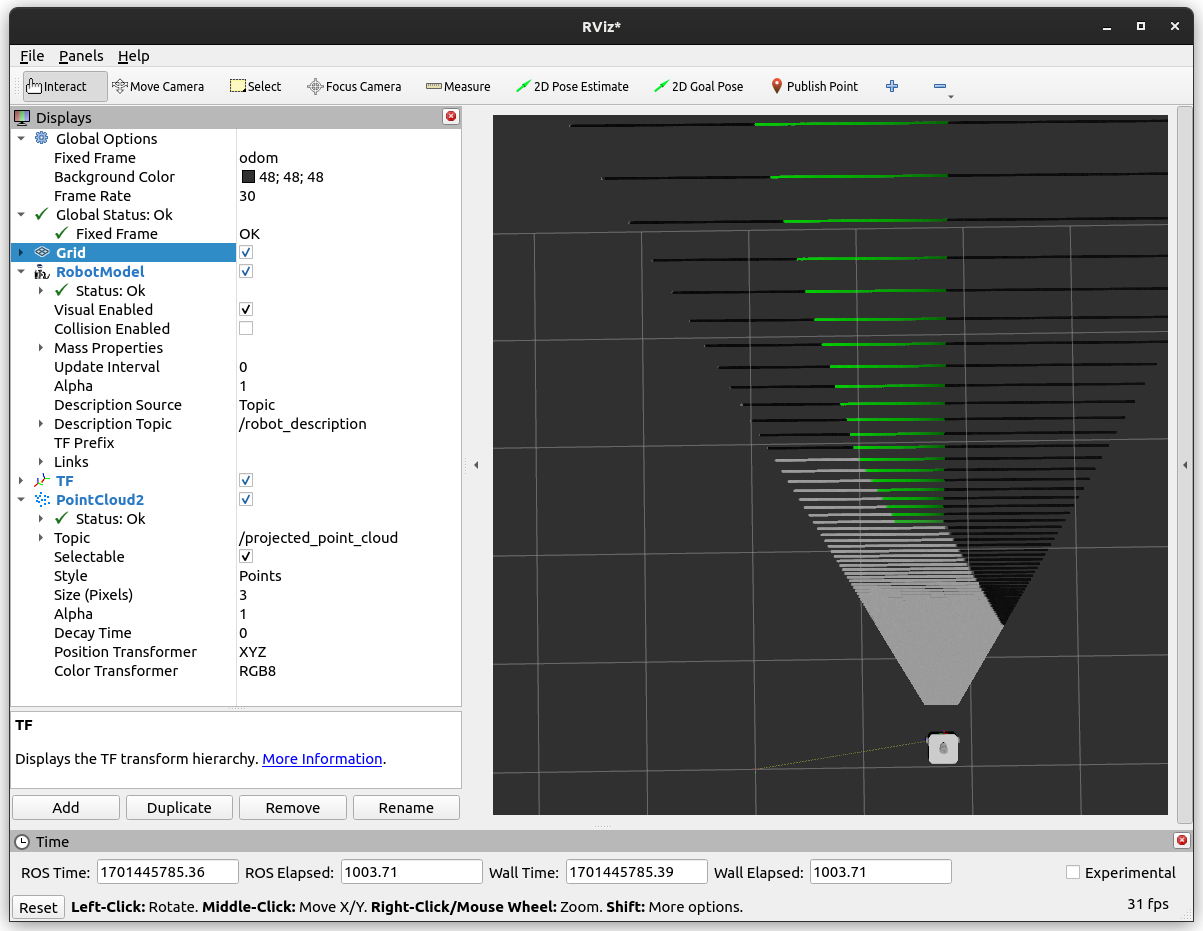
You can now move the robot around in Gazebo and see the projection change in RViz. Note that the projection is only useful for things close to the ground plane. To move the robot around you can use the following command:
ros2 run turtlebot3_teleop teleop_keyboard
You could see the following view in RViz after moving the robot around:
If you are using a camera with significant distortion and don’t rectify the image, you can set the use_distortion ROS parameter to true to use the distortion model from the camera info message in the projection.
IPM Library
In this part of the tutorial, we will learn how to use the IPM library directly. We will write a small Python script that will project a list of points onto a given plane. It will be assumed that you have a working ROS 2 installation and performed the steps in Installation. Also don’t forget to source your ROS 2 installation as well as the IPM workspace.
First of all, we manually publish a tf frame that shows the spatial relationship between our camera and the plane we want to project onto. In a real-world scenario, this would be already present in the tf tree of your robot setup, but for this toy example, we will publish it manually.
ros2 run tf2_ros static_transform_publisher 0 0 -1 0 0 0 1 map camera_optical_frame
Project a single point
Now we can write our Python script (ipm_example.py), where we will project given pixels onto the plane. Please read the comments in the code to understand what is needed for the projection and where one needs to be careful.
import rclpy
import tf2_ros as tf2
from builtin_interfaces.msg import Time
from geometry_msgs.msg import PointStamped
from ipm_library.exceptions import NoIntersectionError
from ipm_library.ipm import IPM
from rclpy.node import Node
from sensor_msgs.msg import CameraInfo
from shape_msgs.msg import Plane
from std_msgs.msg import Header
from vision_msgs.msg import Point2D


class IPMExample(Node):
    def __init__(self):
        # Let's initialize our node
        super().__init__('ipm_example')

        # We will need to provide the camera's intrinsic parameters to perform the projection
        # In a real scenario, this would be provided by the camera driver on a topic
        # If you don't know the intrinsic parameters of your camera,
        # you can use the camera_calibration ROS package to calibrate your camera
        self.camera_info = CameraInfo(
            header=Header(
                # This defines where the camera is located on the robot
                frame_id='camera_optical_frame',
            ),
            width=2048,
            height=1536,
            k=[1338.64532, 0., 1026.12387, 0., 1337.89746, 748.42213, 0., 0., 1.],
            d=[0., 0., 0., 0., 0.] # The distortion coefficients are optional
        )

        # We want to publish the projected points on a topic so we can visualize them in RViz
        self.point_pub = self.create_publisher(PointStamped, 'ipm_point', 10)

        # A TF buffer is needed as we need to know the spatial relationship between the camera and the plane
        self.tf_buffer = tf2.Buffer()
        self.tf_listener = tf2.TransformListener(self.tf_buffer, self, spin_thread=True)

        # Initialize the IPM library with a reference to the forward kinematics of the robot
        # We also need to provide the camera info, this is optional during the initialization
        # as it can be provided via a setter later on as well
        # We can also set the distortion parameter to True if we want to use the distortion model
        # from the camera info and don't want to rectify the image beforehand
        self.ipm = IPM(self.tf_buffer, self.camera_info, distortion=True)

        # We will now define the plane we want to project onto
        # The plane is defined by a normal and a distance to the origin
        # following the plane equation ax + by + cz + d = 0
        self.plane = Plane()
        self.plane.coef[2] = 1.0  # Normal in z direction

    def main(self):
        while rclpy.ok():
            # We will ask the user for a pixel to project
            point = Point2D(
                x = float(input('Enter pixel x: ')),
                y = float(input('Enter pixel y: '))
            )

            # Use the latest time for TF
            # Note that this is not the correct way to do this, but it is sufficient for this example
            # Normally, you would use the timestamp of the image/measurement you want to project
            # This is relevant as the tf tree is time-dependent and might change over time as the robot moves
            # This can lead to wrong projections, especially close to the horizon where the projection is very sensitive
            time = Time()

            # We will now project the pixel onto the plane using our library
            try:
                point = self.ipm.map_point(
                    self.plane,
                    point,
                    time,
                    plane_frame_id='map', # We defined a transform from the map to the camera earlier
                    output_frame_id='map' # We want the output to be in the same frame as the plane
                )

                # Print the result
                print(f'Projected point: {point.point.x}, {point.point.y}, {point.point.z}')

                # Now we will publish the projected point on a topic so we can visualize it in RViz
                self.point_pub.publish(point)
            except NoIntersectionError:
                print('No intersection found')


if __name__ == '__main__':
    rclpy.init()
    ipm_example = IPMExample()
    ipm_example.main()
    rclpy.shutdown()
Warning
Don’t use this snipped for large numbers of points. To project many points (like all pixels in an image) use the following snipped, which utilizes NumPy and calls e.g. TF only once for all of them.
Now that we have our script, we can run it using the following command:
python3 ipm_example.py
In a proper ROS environment, one would put this into a ROS package, declare all dependencies, and run it using the ROS 2 launch system. We skip this for now for the simplicity of this tutorial.
It will ask you for a pixel to project and then publish the projected point on the topic ipm_point.
You can e.g. enter the pixel (0, 0) and view the result in RViz by adding a PointStamped display and setting the topic to ipm_point. You can also add the TF display to see the relationship between the camera and the plane’s origin.
To run RViz, use the following command:
rviz2
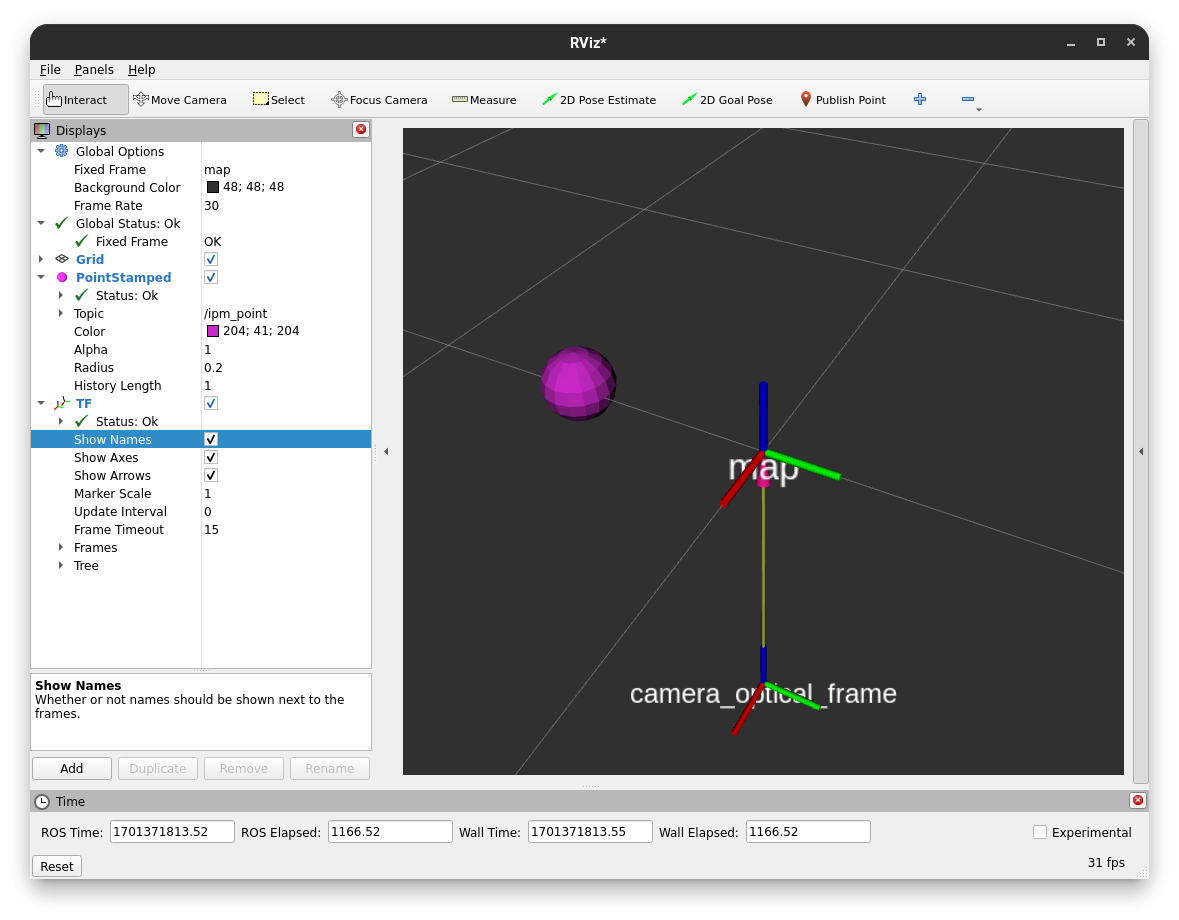
After entering the pixel (0, 0) you should see this result in RViz. You can interpret this as the camera looking from the bottom along the z-axis onto the map plane which has z as its normal vector.
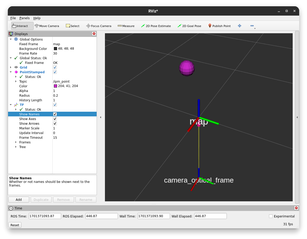
As the camera transform is currently aligned to the world coordinates (i.e. the map), we can enter a pixel with a higher x-position value and see the point moving along the red x-axis to the bottom left. This is not always the case, as the camera can be rotated in any direction, but the simple transform we defined earlier enables this sanity check.
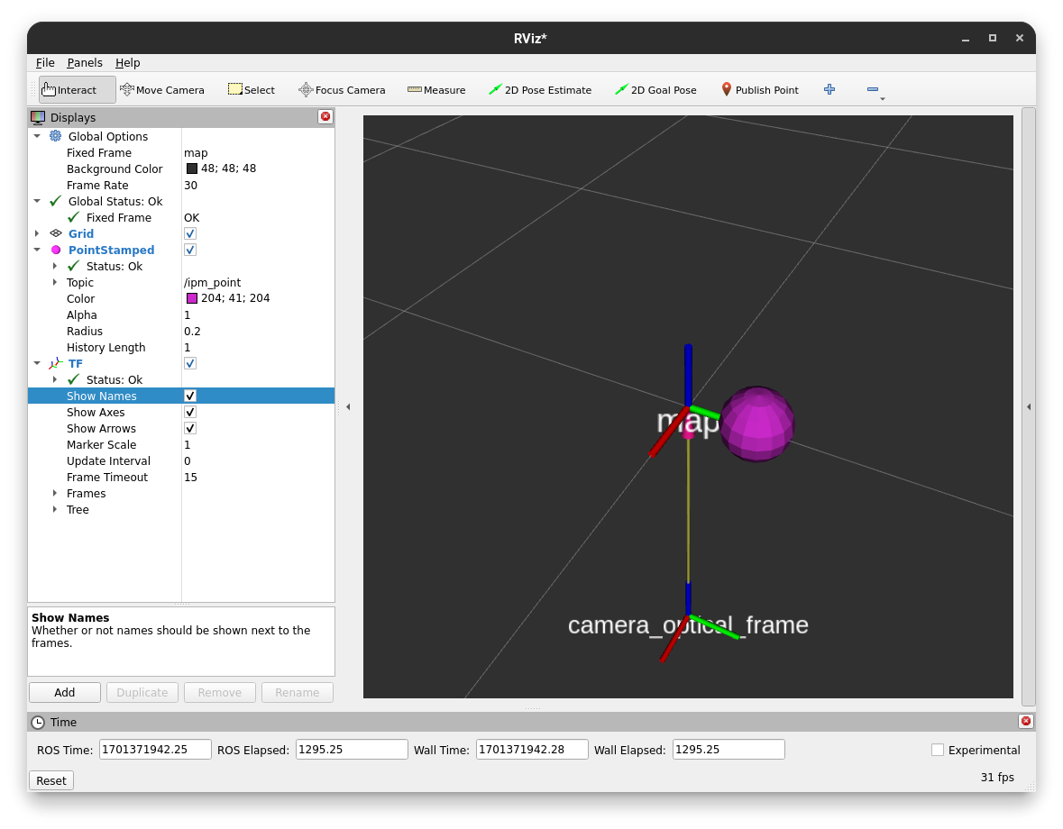
The same is true for the y-axis, but the point will move along the green y-axis.
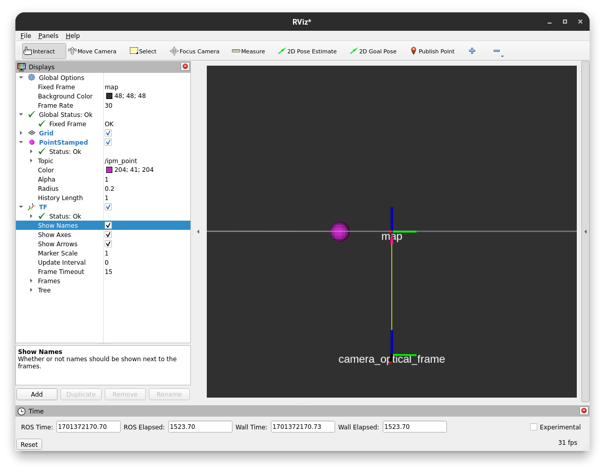
If you align your view with the plane (so you look edge-on), you can see that the point will not move in the z direction.
Project a large number of points at once
We can adapt the script from earlier to efficiently project a number of points at once. In this case, a NumPy array instead of the Point2D ROS message is used as our input data structure.
import numpy as np
import rclpy
import tf2_ros as tf2
import time
from builtin_interfaces.msg import Time
from ipm_library.ipm import IPM
from rclpy.node import Node
from sensor_msgs_py.point_cloud2 import create_cloud_xyz32
from sensor_msgs.msg import CameraInfo, PointCloud2
from shape_msgs.msg import Plane
from std_msgs.msg import Header


class IPMExample(Node):
    def __init__(self):
        # Let's initialize our node
        super().__init__('ipm_example')

        # We will need to provide the camera's intrinsic parameters to perform the projection
        # In a real scenario, this would be provided by the camera driver on a topic
        # If you don't know the intrinsic parameters of your camera,
        # you can use the camera_calibration ROS package to calibrate your camera
        self.camera_info = CameraInfo(
            header=Header(
                # This defines where the camera is located on the robot
                frame_id='camera_optical_frame',
            ),
            width=2048,
            height=1536,
            k=[1338.64532, 0., 1026.12387, 0., 1337.89746, 748.42213, 0., 0., 1.],
            d=[0., 0., 0., 0., 0.] # The distortion coefficients are optional
        )

        # We want to publish the projected points on a topic so we can visualize them in RViz
        self.point_cloud_pub = self.create_publisher(PointCloud2, 'ipm_points', 10)

        # A TF buffer is needed as we need to know the spatial relationship between the camera and the plane
        self.tf_buffer = tf2.Buffer()
        self.tf_listener = tf2.TransformListener(self.tf_buffer, self, spin_thread=True)

        # Initialize the IPM library with a reference to the forward kinematics of the robot
        # We also need to provide the camera info, this is optional during the initialization
        # as it can be provided via a setter later on as well
        # We can also set the distortion parameter to True if we want to use the distortion model
        # from the camera info and don't want to rectify the image beforehand
        self.ipm = IPM(self.tf_buffer, self.camera_info, distortion=True)

        # We will now define the plane we want to project onto
        # The plane is defined by a normal and distance to the origin
        # following the plane equation ax + by + cz + d = 0
        self.plane = Plane()
        self.plane.coef[2] = 1.0  # Normal in z-direction

    def main(self):
        while rclpy.ok():
            # Get all pixel coordinates in the image as an NumPy array
            # Due to RViz getting laggy with too many points, we will only use every 10th-pixel
            points = np.meshgrid(np.arange(0, self.camera_info.width, 10), np.arange(0, self.camera_info.height, 10))
            points = np.stack(points, axis=-1).reshape(-1, 2)

            # Use the latest time for TF
            # Note that this is not the correct way to do this, but it is sufficient for this example
            # Normally, you would use the timestamp of the image/measurement you want to project
            # This is relevant as the tf tree is time-dependent and might change over time as the robot moves
            # This can lead to wrong projections, especially close to the horizon where the projection is very sensitive
            measurement_time = Time()

            # We will now project the pixel onto the plane using our library
            header, mapped_points = self.ipm.map_points(
                self.plane,
                points,
                measurement_time,
                plane_frame_id='map', # We defined a transform from the map to the camera earlier
                output_frame_id='map' # We want the output to be in the same frame as the plane
            )

            # Convert the NumPy array into a point cloud message so we can publish it for visualization
            point_cloud = create_cloud_xyz32(header, mapped_points)

            # Now we will publish the projected points on a topic so we can visualize them in RViz
            self.point_cloud_pub.publish(point_cloud)

            # Sleep a bit
            time.sleep(0.1)


if __name__ == '__main__':
    rclpy.init()
    ipm_example = IPMExample()
    ipm_example.main()
    rclpy.shutdown()
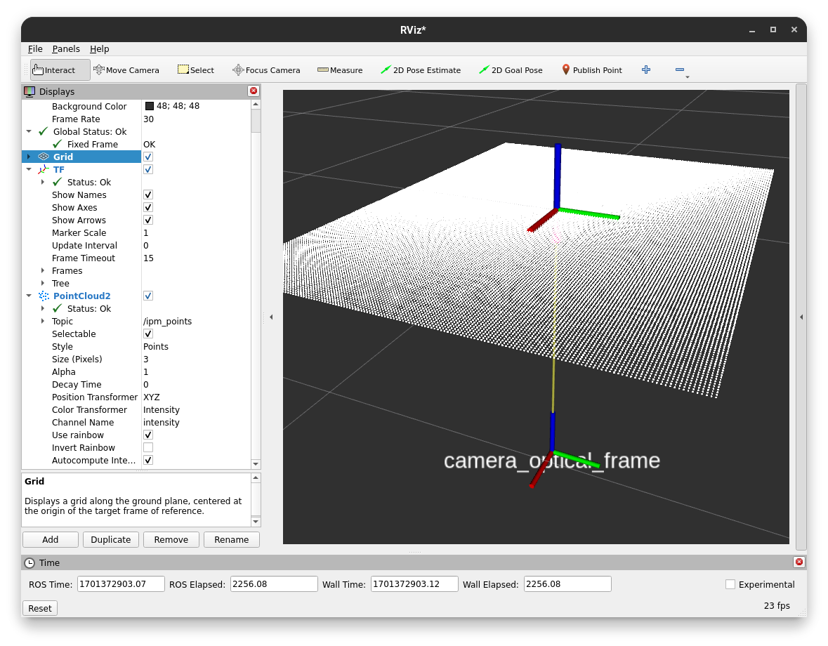
After running this script, you can visualize the result in RViz by adding a PointCloud2 display and setting the topic to ipm_points. You can also set the style to Points for better visibility.
The visualization should look similar to this:
While we project most of our field of view onto the plane, we can see the effects of camera rotations of the projected points. We can adjust our camera transform to see the effects of rotations more clearly. After replacing the dummy transform publisher with the following one, a slight camera rotation along the x-axis is performed.
ros2 run tf2_ros static_transform_publisher 0 0 -1 0.25 0 0 0.97 map camera_optical_frame
Here are the effects on the projection:
Now you should know the basics of the IPM library and how to use it to project points onto a plane using the Python API. In the following sections, we will learn how to use the IPM service and the IPM image node, which are more tightly integrated into the ROS ecosystem and provide a simpler out-of-the-box experience respectively.
IPM Service
While the service adds more overhead it enables tighter integration into the ROS ecosystem and enables compatibility with e.g. C++ code. It also only keeps one TF buffer in case multiple nodes want to share this component.
To launch the IPM service simply run:
ros2 run ipm_service ipm_service
The IPM Service will now listen to the /camera_info topic (you can remap this if you have multiple cameras or another camera namespace) and provide two services. One service for projecting single Point2D points and another to project point clouds in an efficient manner.
As we are currently in a dummy setup we publish the camera info manually by running the following command:
ros2 topic pub /camera_info sensor_msgs/msg/CameraInfo "header:
  stamp:
   sec: 0
   nanosec: 0
  frame_id: 'camera_optical_frame'
height: 1536
width: 2048
distortion_model: 'pinhole'
k:
  - 1338.64532
  - 0.0
  - 1026.12387
  - 0.0
  - 1337.89746
  - 748.42213
  - 0.0
  - 0.0
  - 1.0"
We also need a transform from the camera to the plane. For now, we do a simple dummy static transform. Later on, this will be dynamically provided by the tf tree connecting the camera frame with the projection plane (e.g. the ground).
ros2 run tf2_ros static_transform_publisher 0 0 -1 0 0 0 1 map camera_optical_frame
Now we can open rqt and load the Service Caller plugin (Plugins > Services > Service Caller). This way we can test the service without writing any scripts. Later on, the service is obviously called in your code, but for now, we keep using the gui.
After selecting the /map_point service you should see the following view. Enter the values accordingly. For now, you can use a 0 time to use the latest transform available. Note that this is a bad idea in most real-world applications and you want to use the time stamp of your measurement (e.g. image) instead.
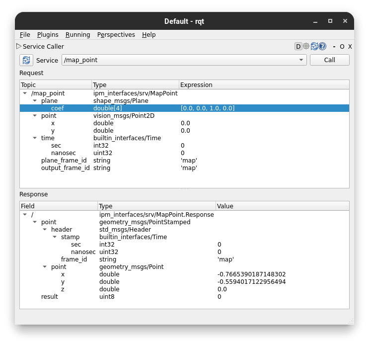
You should get a response with the same values compared to calling the Python API directly with the script in IPM Library. The service definitions are from the ipm_interfaces in the IPM repo. Look there if you get any non-zero results.
The IPM service also provides a fast way to project many points at once without resulting in too many service calls. You can use the /map_points service, which accepts a point cloud as input.
Similarly to the ipm_image_node, you can set the use_distortion ROS parameter to true to use the distortion model from the camera info in the projection and not rectify the image beforehand.